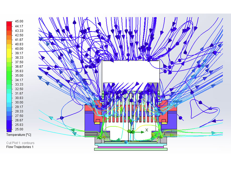
Thermal Simulation
Heat is generated when current flows through the device under test (DUT) from test system. It can damage the DUT performance if there is no proper thermal solution. Excessive heat might cause the DUT to slow down its operation speed. In worst case scenario, smoke is emitted, DUT can be burnt and melt into the test socket. To avoid these effects and damage, thermal analysis is performed to study the temperature distribution and heat transfer between systems, and to provide solution to maintain the DUT at or below the given temperature during testing.
TTS integrates the Computational Fluid Dynamics (CFD) method to simulate the heat transfer between DUT, hand socket lid and test socket; at design stage, with a series of boundary conditions, using steady state or transient response. Steady-state thermal analysis refers to linear static analysis where the heat flow does not change over time while transient thermal analysis is a time-dependent analysis of the heat flow.
The thermal simulation can reveal the following:
- Thermal conduction in solids, convection between fluid and solids, and radiation.
- Heat source: i.e. heat generation rate, heat power, and temperature.
- Detect hot spot in design, reduce overheating problem and thus improve product thermal performance.

Thermal Simulation
Steady State Study
Thermal Simulation
Transient Study

Thermal Simulation
Active Fan Cooling

Thermal Simulation
Active Fan Cooling - Front View
Fan Heatsink (Low Power Dissipation)
Fan Heatsink (Low Power Dissipation)
Swirl Effect Fan Air Flow

Fan Heatsink (Low Power Dissipation)
Linear Effect Fan Air Flow
The use of fan heatsink, where a fan is incorporated with the heatsink base, is intended to increase the localized air flow while improving thermal efficiency. Thermal analysis is performed to analyze the effectiveness of thermal dissipation in heatsink design as well as to optimize fan selection to meet overall thermal performance.
Heat Pipe (High Power Dissipation)
Heat Pipe (HP) heatsink is the combination of a heat pipe and expansion fin heat dissipation technology. HP heatsink offers extremely high effective thermal conductivity where heat generated from high power device can be dissipated with heat pipe thermal solution. The heat pipe thermal analysis is performed to determine the heat capacity that can be transmitted through a heat pipe, and the thermal behaviour and efficiency of the heat pipe in releasing high power heat over the system.
- Package Size : 45mm x 45mm
- Power Dissipation : 215W
- Simulation Study : Steady State

Heat Pipe (High Power Dissipation)

Heat Pipe (High Power Dissipation)
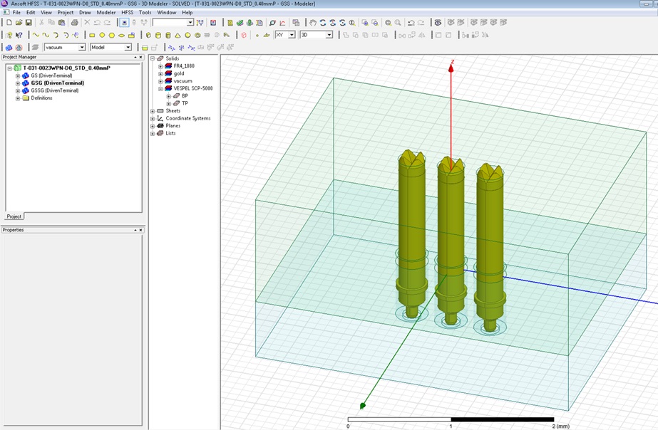
Signal Integrity Simulation
Test probe plays an important role in the semiconductor test system. It helps to transfer -signals to and from device under test (DUT) to tester with minimal attenuation and signal degradation- The critical challenge is to provide high speed signals transfer between the test socket and the DUT. This electrical performance can be analyzed by Signal Integrity (SI) study to help select the best suitable test probe for different testing environment. The main tools we use to study and obtain accurate SI solutions for test probes are Ansoft HFSS (High Frequency Structure Simulator) and Ansoft Designer.

GSG Configuration

GSSG Configuration

Pattern A Configuration

An Example Of SI Simulation Report
SI simulation is usually performed based on testing configuration like GSG, GSSG, and other specific parameters such as socket pitch and material.
Ansoft HFSS
Ansoft HFSS software is used specifically to build a 3D structure, where simulation is based on the actual dimension of testing such as simulation of the connection between IC package, test probe, socket and PCB testing. The outputs from the simulation are on S-parameter such as Insertion Loss, Return Loss, Crosstalk, Inductance, Capacitance and Impedance.
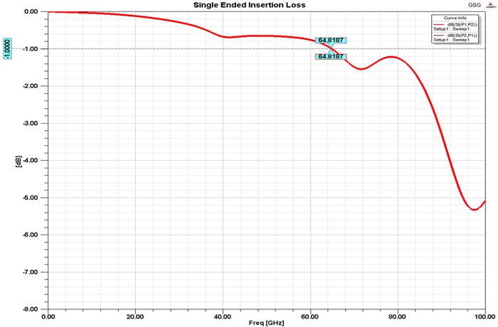
Single Ended Insertion Loss

Single Ended Return Loss

Loop Inductance

Impedance
Ansoft Designer

Ansoft Designer software is used for 2D structure (planar) to convert and simulate S-Parameters from HFSS 3D for run time-domain reflectometry (TDR) analysis.
Finite Element Analysis
In order to bring the best possible solution to the customer, TTS integrates finite element analysis (FEA), a simulation tool to help predict the product performance at the design stage. The FEA simulation includes but not limited to stress and deformation analysis – to determine the strength (Eg. displacement, stress, strain, safety factor) of socket used in test, test printed circuit board (PCB) and device under testing (DUT)]. The use of thermal analysis can reveal the thermal stress effect on the socket structure, when used in a testing environment; whilst the fatigue analysis can determine the yield point of test probe and estimate its life span. With the aid of FEA studies, the weakness of the design can be identified accurately, and to provide an optimal design to the customer.
FEA - Floating Plate Warpage

FEA - Socket Warpage
Test Contactor Warpage
When total pin count and total pin force increase, the stress and displacement of the socket become a major concern. By using FEA tool to provide insight into socket performance, it identifies the physical behaviour of socket warpage, determines the socket maximum stress and predicts the failure in the socket design. The completed design is simply validated in the virtual world with FEA, and corrected at the design stage if necessary before fabrication of the parts.

Figure 1 : Plot Y-Displacement
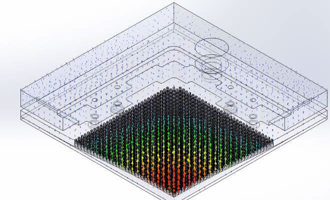
Figure 2 : Vector Plot Resultant Displacement
Multi Test Site Contactor Warpage
Fine pitch hole, high pin preloaded force, high pin count, and the thinness of socket in the case of the short pin - all of this test scenario may be extreme and indeterminate. FEA structural simulation is performed to determine the stress and potential deformation of multi test site contactor.

Figure 3 : Plot Y-Displacement

Figure 4 : Vector Plot Resultant Displacement
Floating Plate Warpage
Floating plate functions as a fine guide and acts as a self-alignment between package balls to pin final guide. High insertion force, thinness of the floating plate and high deformation may cause failure in the floating plate. FEA structural simulation is performed to optimize the structural robustness.

Figure 5 : Plot Y-Displacement

Figure 6 : Vector Plot Y-Displacement
Non-Linear & Fatigue analysis for Pin Life Span
Non-linear analysis helps if the design object has complicated geometry or complex material properties. Non-linear analysis problem involves large deformation, varied orientation, and varied loads. For example large deformation caused by compression load on the spring inside the probe pin, will shorten the life span of the spring. FEA tool is used to predict the peak stress of the spring from cycle test where the damage percentage and life span of the spring can be predicted.


")